

Intro
Hey everyone! It has been a while since my last article, but I can blame a new addition to the family for that. In standard sleep deprived fashion, I thought it would be fun to snag some new gear and conduct some tests. Today, I am going to be going through my time with the TP Link TL-WR841N router (I promise this is not an affiliate link. Amazon, if you are listening and we know that you are, let me get those royalties 😉 ).
Visual Inspection
First and foremost, I like to conduct a visual inspection of the hardware that I am working with. As silly as this seems, there is a lot of useful information hidden on labels that will be helpful throughout your engagement.
I first like to flip my device over and check for the FCC filing ID. This will help in my ability to get higher resolution photos of all of the chips on the device. As seen below, I have my FCC ID (2AXJ4WR841NV14) in size 0.0001 font. Pro-Tip: take a photo with your phone camera and zoom in, you will be surprised how well this works for small font and chip identification.

Once we identified our FCC ID, you can use either of the two links to search for detailed schematics, internal photos, and more!
After my initial visual inspection, time to pop this thing open. With two screws, a spudger, and a little brute force, bingo!

Upon my initial inspection, there are a few things that stand out right away. I also reference back to my FCC photos to validate my observations. As labeled above, I provide a breakdown of each item of interest to me.
PCB Layout
- A: CPU
- B: RAM
- C: SPI/Flash/ROM
- D: UART
- E: Ground pad
PCB UART Connection Analysis
UART Connection Identification: Observed a 4-pin test connection labeled VCC, GND, RX, and TX (Detail D), indicating a likely UART interface.
PCB Operating Voltage: Measured a 9V voltage drop across the input jack using a multimeter, confirming the PCB’s operating voltage.
Ground Verification: Confirmed ground connection on P1 (Detail E) by testing continuity with the ground on the input jack.
UART Pin Testing
- VCC: Measured 3.3V voltage drop between VCC and ground, verifying UART operates at 3.3V.
- GND: Confirmed continuity between UART GND pin and known board ground, validating it as a ground connection.
- RX: Recorded 0V voltage drop between RX and ground; continuity test with known ground showed no connection, as expected.
- TX: Measured ~3.3V voltage drop between TX and ground during normal operation.
UART Activity Confirmation: Monitored TX pin during router power cycle; observed voltage fluctuations between ~1V and 3V, indicating active data transmission during bootup.
Conclusion: Based on pin labeling, voltage measurements, and TX activity, the connection is confirmed as a UART interface.
UART Shell
After conducting my analysis on the UART connection and validating that it is an active connection on the TX/RX pins, I decided to hook up a serial adapter and see if I could read boot logs.
Immediately after booting my screen session and powering on the router, I am getting great bootloader logs!
A few things immediately stood out to me, U-Boot 1.1.3 and 3: System Boot system code via Flash.(0xbc010000), which gives me an idea that I can button mash some keystrokes for a boot interrupt?
<--snip-->
U-Boot 1.1.3 (Feb  3 2021 - 10:10:08)

Board: Ralink APSoC DRAM:  32 MB
relocate_code Pointer at: 81fc0000
flash manufacture id: 1c, device id 70 16
Warning: un-recognized chip ID, please update bootloader!
============================================
Ralink UBoot Version: 4.3.0.0
--------------------------------------------
ASIC 7628_MP (Port5<->None)
DRAM component: 256 Mbits DDR, width 16
DRAM bus: 16 bit
Total memory: 32 MBytes
Flash component: SPI Flash
Date:Feb  3 2021  Time:10:10:08
============================================
icache: sets:512, ways:4, linesz:32 ,total:65536
dcache: sets:256, ways:4, linesz:32 ,total:32768

 ##### The CPU freq = 580 MHZ ####
 estimate memory size =32 Mbytes
RESET MT7628 PHY!!!!!!
continue to starting system.
0
disable switch phyport...

3: System Boot system code via Flash.(0xbc010000)
do_bootm:argc=2, addr=0xbc010000
## Booting image at bc010000 ...
   Uncompressing Kernel Image ... OK
No initrd
## Transferring control to Linux (at address 8000c150) ...
## Giving linux memsize in MB, 32

Starting kernel ...
[ util_execSystem ] 141:  oal_wlan_ra_initWlan cmd is "ifconfig ra0 up"

[RTMPReadParametersHook:297]wifi read profile faild.

<--snip-->
After doing some digging on TP Link U-Boot implementations, I found that TP Link embeds a Serial command TPL to interrupt the bootloader menu. Giving this a go, it unfortunately did not result in much as the U-Boot capability was severely stripped down and did not allow for valuable or useful commands.
switch BootType:

4: System Enter Boot Command Line Interface.

U-Boot 1.1.3 (Feb  3 2021 - 10:10:08)
MT7628 # help
Unknown command 'help' - try 'help'
MT7628 #
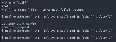
Back to the standard UART shell, I checked to see what user privileges I had. Thankfully, this was a quick and easy win as UART shell was root by default!
Moving on from my user check, I thought it would be a good time to view the /bin directory to view what apps I can potentially leverage for the rest of my investigation. As I previously saw in the boot messages, the router is running BusyBox, which is very common on Embedded Linux devices. The first step was to check how stripped down it was and see what commands were available to me.
Something immediately stood out to me and that was the use of tftp which I had the thought of potentially uploading a un-restricted instance of BusyBox on the router to use more commands.
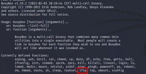
Using our previously identified architecture type, I know this is mipsel so I am able to utilize the built in tftp service on the router to upload our “payload”.
Transferring BusyBox
- Find a local directory on the router that allows for write privileges
- Create a folder to store your working items such as a
_toolsin the/tmpdirectory - TFTP the default BusyBox binary to the router with the steps below:
tftp -r busybox-mipsel -g <localIP>
chmod 777 busybox-mipsel
# Bonus!! Leverage NC for a better UART shell
./busybox-mipsel nc <localIP> 4444
BusyBox Enumeration
Now that I have a fully working instance of BusyBox at my disposal, it is time for some file enumeration, looking for juicy stuff!
Below are some examples of rudimentary checks that I like to run on my file system which could help me identify passwords, usernames, API keys, and sensitive file types.
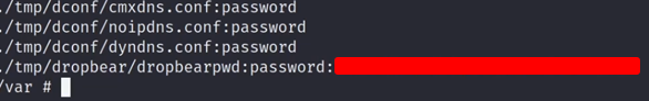
Passwords
/var/tmp/_tools/busybox-mipsel grep -r 'pass' .
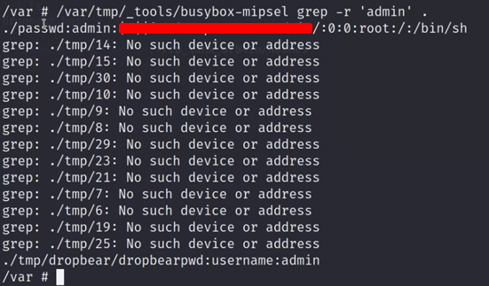
Usernames
/var/tmp/_tools/busybox-mipsel grep -r 'admin' .
APIs
/var/tmp/_tools/busybox-mipsel grep -r 'api' .
/var/tmp/_tools/busybox-mipsel grep -r 'key' .
Files
/var/tmp/_tools/busybox-mipsel find -name '*.xml'
/var/tmp/_tools/busybox-mipsel find -name '*.conf'For the most part, I did not get too much out of this but I did manage to get some hashes that I attempted to crack later with no success:
SPI and Flash Enumeration
Moving on from our UART enumeration for now, I figured it was time to dump the firmware from our SPI Flash chip and see what else we could find.
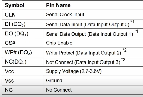
Referencing back to my chip schematics, it seemed to be a pretty standard SPI 8-Pin Chip layout. It was time to hook up the CH341a programmer with a SOIC clip and see what we could find.
My first step was to shoot blind and hope an automatic Flashrom extraction would work, and of course, it did!
flashrom -p ch341a_spi -r <firmware.bin>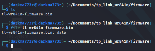
Now that I have a valid firmware extract, it was time to run binwalk to extract the contents of the firmware and start digging through the file-system.
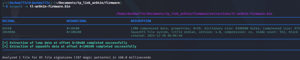
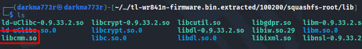
Quickly browsing through my squashfs extract, most of our findings matched that of our UART enumeration. I did want to spend some extra time in our /lib folder as it contains shared object libraries that could be of interest to me. My thought process for this was, upon my initial observations, there were a few xml files that were encrypted using some internal library/code.
They may not contain useful information, but curiosity got the best of me and thought it would be a good idea to spend countless hours going through shared objects….
Saving you 10 hours of digging, I found a shared object libcmm.so that contained string matches for decrypt!
Reverse Engineering
Time to build out a project in Ghidra and pull open our libcmm.so file and see if we can’t RE this decryption key!
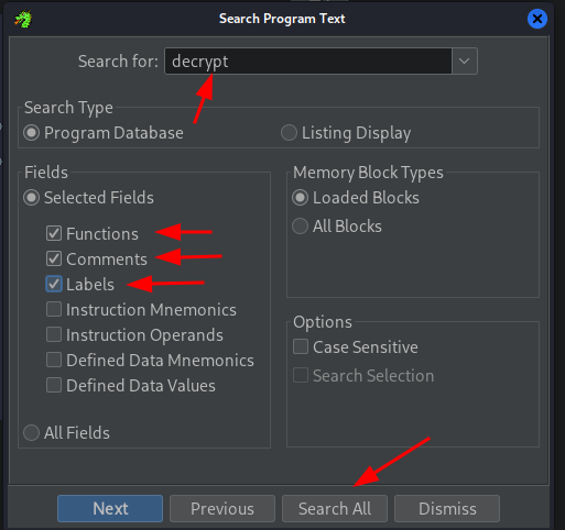
My first step to this process was pretty elementary and hack-y. Running a quick Program Text search for “decrypt” to find a possible label or function in the shared object that could lead me down the right path.
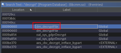
Lucky for me, I immediately had a hit that stood out like a sore thumb. With a quick double click, we are dropped right to our function!
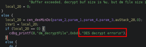
The best news of the day was, this was a generic DES encryption with the use of OpenSSL and the key, is super easy to crack! Lets take a look.
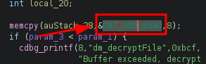
Alright, this is looking great for me now! Checking out the details of this variable and storage array, I find what I believe is our decryption key! (Note: double clicking in Ghidra will automatically navigate to your variable, function, etc)
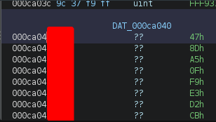
Time to test drive this thing and see if it works on our encrypted config and xml files!
First up is a default_config.xml file that while may contain nothing, it was worth a shot. I went through all of that effort so I wanted to see “is the juice worth the squeeze”…spoiler, it wasn’t.
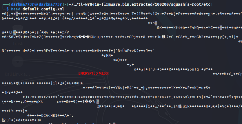
Getting our OpenSSL command built out with a little Google Greasing, we come up with:
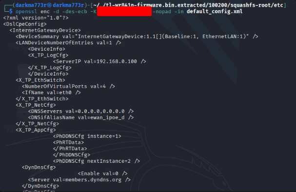
openssl enc -d -des-ecb -K <redacted> -nopad -in default_config.xmlLets see how this works, fingers crossed at this time!
SUCCESS!!
Conclusion
At this time, I am riding on a nice wave and going out on a high. Is there more to enumerate and reverse engineer, sure. Will I revisit this router in the future, absolutely.
This was a really fun project and a great learning experience for me. I tried to keep it as short and concise as possible for the two readers that may read this… 😉
I appreciate you taking the time to go through this journey with me and I plan to get a few more of these out, time pending with the little ones.
Up Next: Medical Devices!
Cheers,
Darkma773r